Week 8 [Fri, Mar 8th] - Topics
Guidance for the item(s) below:
Soon, you will start writing automated Java tests for your project.
First, let us learn such testing fits into an aspect called developer testing of the testing landscape.
Can explain the need for early developer testing
Delaying testing until the full product is complete has a number of disadvantages:
- Locating the cause of a test case failure is difficult due to the larger search space; in a large system, the search space could be millions of lines of code, written by hundreds of developers! The failure may also be due to multiple inter-related bugs.
- Fixing a bug found during such testing could result in major rework, especially if the bug originated from the design or during requirements specification i.e. a faulty design or faulty requirements.
- One bug might 'hide' other bugs, which could emerge only after the first bug is fixed.
- The delivery may have to be delayed if too many bugs are found during testing.
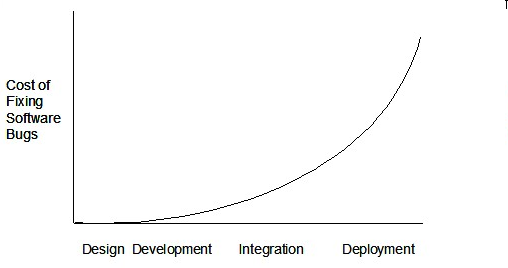
Therefore, it is better to do early testing, as hinted by the popular rule of thumb given below, also illustrated by the graph below it.
The earlier a bug is found, the easier and cheaper to have it fixed.
Such early testing software is usually, and often by necessity, done by the developers themselves i.e., developer testing.
Guidance for the item(s) below:
The sections below gives an overview of test automation, something used heavily in developer testing.
Can explain test automation tools
JUnit is a tool for automated testing of Java programs. Similar tools are available for other languages and for automating different types of testing.
This is an automated test for a Payroll class, written using JUnit libraries.
    // other test methods

    @Test
    public void testTotalSalary() {
        Payroll p = new Payroll();

        // test case 1
        p.setEmployees(new String[]{"E001", "E002"});
        assertEquals(6400, p.totalSalary());

        // test case 2
        p.setEmployees(new String[]{"E001"});
        assertEquals(2300, p.totalSalary());

        // more tests...
    }
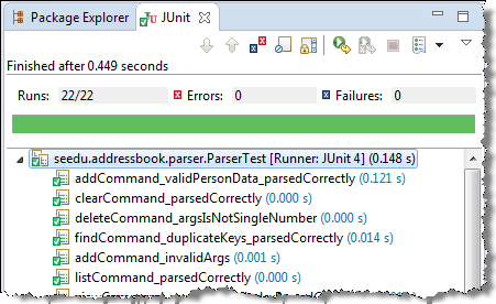
Most modern IDEs have integrated support for testing tools. The figure below shows the JUnit output when running some JUnit tests using the Eclipse IDE.
Guidance for the item(s) below:
Now, let us learn about JUnit, a tool used for automated testing. JUnit is a third-party tool (not included in the JDK). but your tP project is already configured to use JUnit, with the help of Gradle. That means the video tutorial given at the end of the section is mostly not applicable to you, unless you are interested to learn how to set up a non-Gradle project for JUnit.
Follow up notes for the item(s) above:
Quoting from tP instructions:
We recommend that each person adds some JUnit tests to test their tP code.
Some examples from AddressBook-Level2:
seedu.addressbook.common.Utils.java
Tests:seedu.addressbook.common.UtilsTest.java
Note how the test class is in the same package as the SUT (although in a different folder). Advantage: the test class has access to all non-private members of the SUT, including package private members.- SUT:
seedu.addressbook.parser.Parser.java
Tests:seedu.addressbook.parser.ParserTest.java
Note how some of the test methods follow a different naming convention e.g.,parse_emptyInput_returnsIncorrect(). Cross-check the coding standard to confirm if this naming convention is allowed.- SUT:
seedu.addressbook.data.AddressBook.java
Tests:seedu.addressbook.data.AddressBookTest.java
Guidance for the item(s) below:
As you will be updating documentation of your project soon, here are some guidelines to help you with that.
Guidance for the item(s) below:
Software engineers often have to write developer documentation to explain their work to others. One important objective of developer documentation is to explain the design and the implementation of the software, which usually uses diagrams as models of the design being described.
Let's learn what models are, and how they are useful even beyond mere documentation.
Guidance for the item(s) below:
Can explain structure modeling of OO solutions
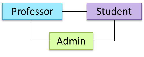
An OO solution is basically a network of objects interacting with each other. Therefore, it is useful to be able to model how the relevant objects are 'networked' together inside a software i.e. how the objects are connected together.
Given below is an illustration of some objects and how they are connected together. Note: the diagram uses an ad-hoc notation.
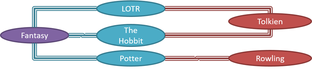
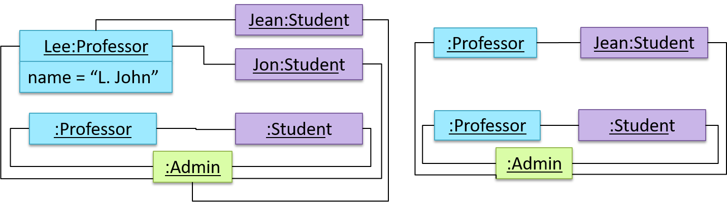
Note that these object structures within the same software can change over time.
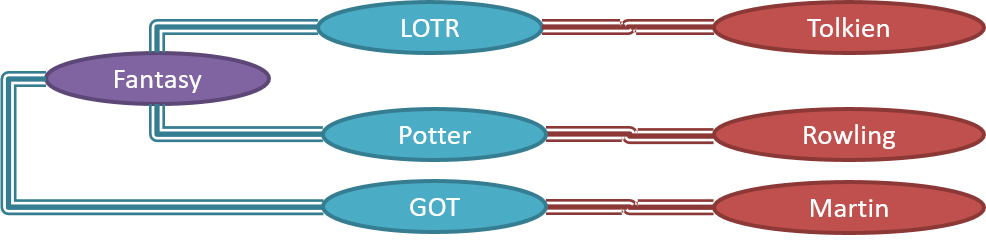
Given below is how the object structure in the previous example could have looked like at a different time.
However, object structures do not change at random; they change based on a set of rules set by the designer of that software. Those rules that object structures need to follow can be illustrated as a class structure i.e. a structure that exists among the relevant classes.
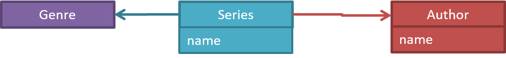
Here is a class structure (drawn using an ad-hoc notation) that matches the object structures given in the previous two examples. For example, note how this class structure does not allow any connection between Genre objects and Author objects, a rule followed by the two object structures above.

UML Object Diagrams model object structures. UML Class Diagrams model class structures.
Here is an object diagram for the above example:
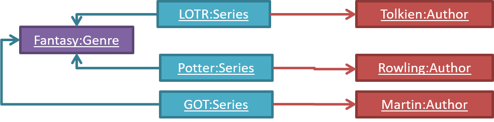
And here is the class diagram for it:
Can use basic-level class diagrams
Contents related to UML diagrams in the panels given below belong to a different chapter (i.e., the chapter dedicated to UML); they have been embedded here for convenience.
Classes form the basis of class diagrams.
Associations are the main connections among the classes in a class diagram.
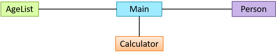
The most basic class diagram is a bunch of classes with some solid lines among them to represent associations, such as this one.
An example class diagram showing associations between classes.
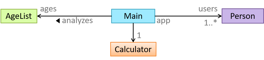
In addition, associations can show additional decorations such as association labels, association roles, multiplicity and navigability to add more information to a class diagram.
Here is the same class diagram shown earlier but with some additional information included:
Guidance for the item(s) below:
Object diagrams complement class diagrams, and therefore, they are covered together with class diagrams.
Can distinguish between class diagrams and object diagrams
Compared to the notation for class diagrams, object diagrams differ in the following ways:
- Show objects instead of classes:
- Instance name may be shown
- There is a
:before the class name - Instance and class names are underlined
- Methods are omitted
- Multiplicities are omitted. Reason: an association line in an object diagram represents a connection to exactly one object (i.e., the multiplicity is always 1).
Furthermore, multiple object diagrams can correspond to a single class diagram.
Both object diagrams are derived from the same class diagram shown earlier. In other words, each of these object diagrams shows ‘an instance of’ the same class diagram.
When the class diagram has an inheritance relationship, the object diagram should show either an object of the parent class or the child class, but not both.
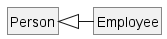
Suppose Employee is a child class of the Person class. The class diagram will be as follows:
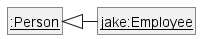
Now, how do you show an Employee object named jake?
 This is not correct, as there should be only one object.
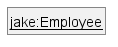 This is OK.
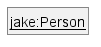 This is OK, as
 jakeis aPersontoo. That is, we can show the parent class instead of the child class if the child class doesn't matter to the purpose of the diagram (i.e., the reader of this diagram will not need to know thatjakeis in fact anEmployee).
Association labels/roles can be omitted unless they add value (e.g., showing them is useful if there are multiple associations between the two classes in concern -- otherwise you wouldn't know which association the object diagram is showing)
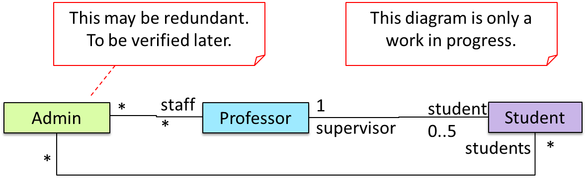
Consider this class diagram and the object diagram:
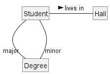
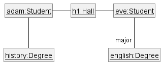
We can clearly see that both Adam and Eve lives in hall h1 (i.e., OK to omit the association label lives in) but we can't see if History is Adam's major or his minor (i.e., the diagram should have included either an association label or a role there). In contrast, we can see Eve is an English major.
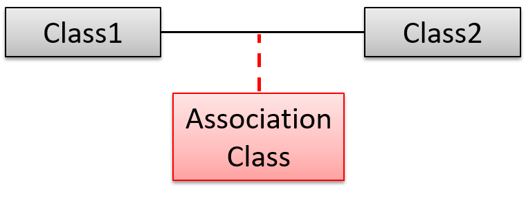
Association Classes
Can interpret association classes in class diagrams
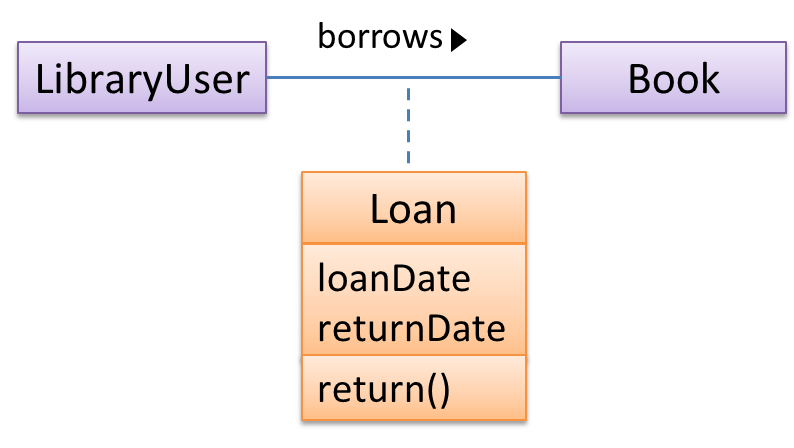
Association classes are denoted as a connection to an association link using a dashed line as shown below.
In this example Loan is an association class because it stores information about the borrows association between the User and the Book.
Guidance for the item(s) below:
Coordinating a team project is not easy. Given below are some very basic tools and techniques that are often used in planning, scheduling, and tracking projects.
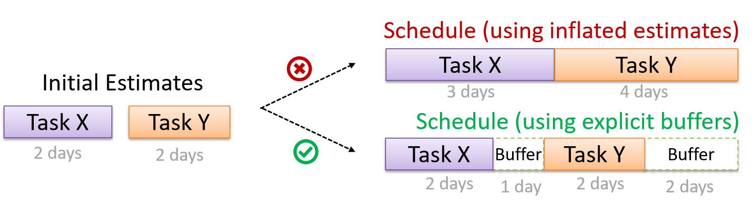
Can explain buffers
A buffer is time set aside to absorb any unforeseen delays. It is very important to include buffers in a software project schedule because effort/time estimations for software development are notoriously hard. However, do not inflate task estimates to create hidden buffers; have explicit buffers instead. Reason: With explicit buffers, it is easier to detect incorrect effort estimates which can serve as feedback to improve future effort estimates.
Can explain issue trackers
Keeping track of project tasks (who is doing what, which tasks are ongoing, which tasks are done etc.) is an essential part of project management. In small projects, it may be possible to keep track of tasks using simple tools such as online spreadsheets or general-purpose/light-weight task tracking tools such as Trello. Bigger projects need more sophisticated task tracking tools.
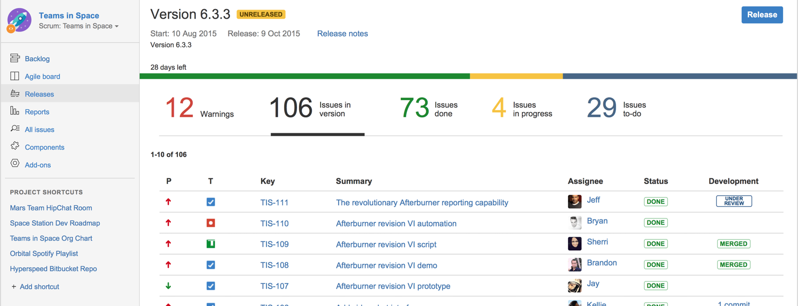
Issue trackers (sometimes called bug trackers) are commonly used to track task assignment and progress. Most online project management software such as GitHub, SourceForge, and BitBucket come with an integrated issue tracker.
A screenshot from the Jira Issue tracker software (Jira is part of the BitBucket project management tool suite):
Guidance for the item(s) below:
GANTT Charts and PERT charts are popular tools in the project management domain but they are rarely useful in small software projects. Hence, they are not included in CS2113 syllabus but it is useful to know at least their names and how they look like.
Guidance for the item(s) below:
This topic is included in the syllabus just to let you know that teams can be structured in different ways.
Which of them is closest to the structure of your team?
Can explain common team structures
Given below are three commonly used team structures in software development. Irrespective of the team structure, it is a good practice to assign roles and responsibilities to different team members so that someone is clearly in charge of each aspect of the project. In comparison, the ‘everybody is responsible for everything’ approach can result in more chaos and hence slower progress.
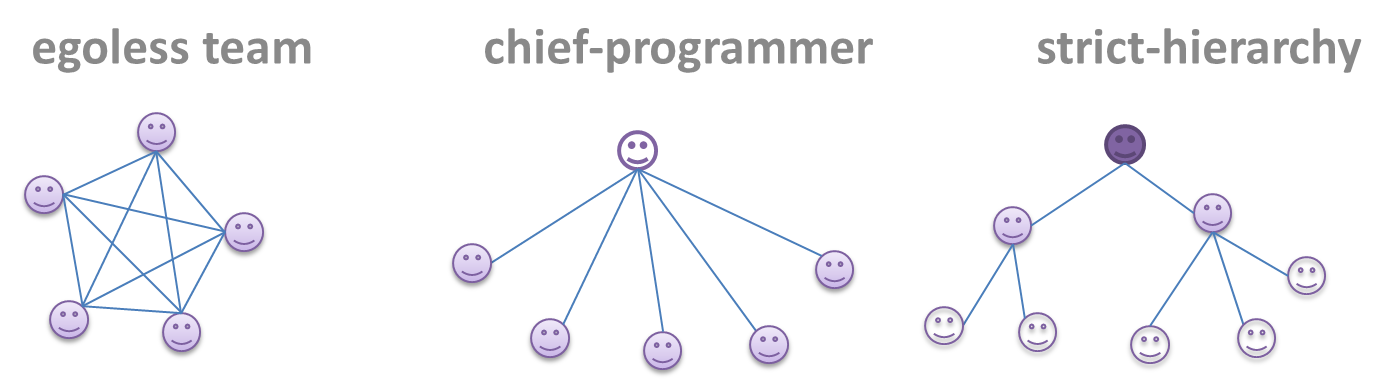
Egoless team
In this structure, every team member is equal in terms of responsibility and accountability. When any decision is required, consensus must be reached. This team structure is also known as a democratic team structure. This team structure usually finds a good solution to a relatively hard problem as all team members contribute ideas.
However, the democratic nature of the team structure bears a higher risk of falling apart due to the absence of an authority figure to manage the team and resolve conflicts.
Chief programmer team
Frederick Brooks proposed that software engineers learn from the medical surgical team in an operating room. In such a team, there is always a chief surgeon, assisted by experts in other areas. Similarly, in a chief programmer team structure, there is a single authoritative figure, the chief programmer. Major decisions, e.g. system architecture, are made solely by him/her and obeyed by all other team members. The chief programmer directs and coordinates the effort of other team members. When necessary, the chief will be assisted by domain specialists e.g. business specialists, database experts, network technology experts, etc. This allows individual group members to concentrate solely on the areas in which they have sound knowledge and expertise.
The success of such a team structure relies heavily on the chief programmer. Not only must he/she be a superb technical hand, he/she also needs good managerial skills. Under a suitably qualified leader, such a team structure is known to produce successful work.
Strict hierarchy team
At the opposite extreme of an egoless team, a strict hierarchy team has a strictly defined organization among the team members, reminiscent of the military or a bureaucratic government. Each team member only works on his/her assigned tasks and reports to a single “boss”.
In a large, resource-intensive, complex project, this could be a good team structure to reduce communication overhead.