This site is from a past semester! The current version will be here when the new semester starts.

Week 10 [Fri, Mar 22nd] - Topics

Detailed Table of Contents


Guidance for the item(s) below:

Good news: this will the the last installment of UML notations.
Bad news: we are going to cover an entire new diagram type in one go (reason: to give you more time to use them in project documentation).

[W10.1] Sequence Diagrams: Basics

W10.1a

Design → Modelling → Modelling Behaviors → Sequence diagrams - basic

Can draw basic sequence diagrams

Sequence diagrams model the interactions between various entities in a system, in a specific scenario. Modelling such scenarios is useful, for example, to verify the design of the internal interactions is able to provide the expected outcomes.

Some examples where a sequence diagram can be used:

To model how components of a system interact with each other to respond to a user action.

To model how objects inside a component interact with each other to respond to a method call it received from another component.

Contents related to UML diagrams in the panels given below belong to a different chapter (i.e., the chapter dedicated to UML); they have been embedded here for convenience.

UML Sequence Diagrams → Introduction

Loading...

UML Sequence Diagrams → Basic Notation

Loading...

UML Sequence Diagrams → Loops

Loading...

UML Sequence Diagrams → Object Creation

Loading...

UML Sequence Diagrams → Minimal Notation

Loading...


Exercises:

Explain Sequence Diagram about Machine


Draw a Sequence Diagram for the code (PersonList, Person, Tag)


Find notation errors in Sequence Diagram


[W10.2] Sequence Diagrams: Intermediate-Level

W10.2a

Design → Modelling → Modelling Behaviors → Sequence diagrams - intermediate

Can draw intermediate-level sequence diagrams

UML Sequence Diagrams → Object Deletion

Loading...

UML Sequence Diagrams → Self-Invocation

Loading...

UML Sequence Diagrams → Alternative Paths

Loading...

UML Sequence Diagrams → Optional Paths

Loading...

UML Sequence Diagrams → Calls to Static Methods

Loading...


Exercises:

What’s going on here?


Explain Sequence Diagram (ParserFactory)


Draw Sequence Diagram for printing a quote


W10.2b

Tools → UML → Sequence Diagrams → Parallel paths

Can interpret sequence diagrams with parallel paths

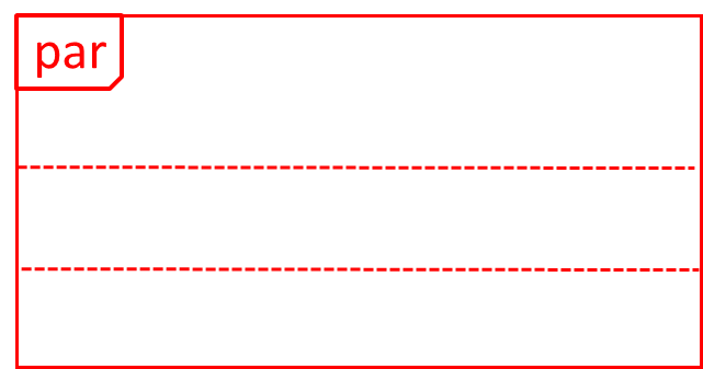
UML uses par frames to indicate parallel paths.

Notation:

Logic is calling methods CloudServer#poll() and LocalData#poll() in parallel.

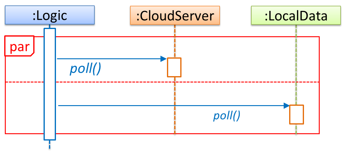
If you show parallel paths in a sequence diagram, the corresponding Java implementation is likely to be multi-threaded because a normal Java program cannot do multiple things at the same time.


W10.2c : OPTIONAL

Tools → UML → Sequence Diagrams → Reference frames


Guidance for the item(s) below:

Previously, you learned:

  • Three basic design quality aspects: abstraction, coupling, cohesion
  • Some design principles (e.g., Single Responsibility Principle) that aim to improve those aspects. There are many more principles but we covered only two (to reduce workload) just to give you a taste only.

This week, we cover design patterns, a concept that builds upon the above. Again, we limit to only two of them, for similar reasons.

[W10.3] Design Patterns


Introduction

Guidance for the item(s) below:

First, let's learn what design patterns are, in general.

W10.3a

Design → Design Patterns → Introduction → What

Can explain design patterns

Design pattern: An elegant reusable solution to a commonly recurring problem within a given context in software design.

In software development, there are certain problems that recur in a certain context.

Some examples of recurring design problems:

Design Context Recurring Problem
Assembling a system that makes use of other existing systems implemented using different technologies What is the best architecture?
UI needs to be updated when the data in the application backend changes How to initiate an update to the UI when data changes without coupling the backend to the UI?

After repeated attempts at solving such problems, better solutions are discovered and refined over time. These solutions are known as design patterns, a term popularized by the seminal book Design Patterns: Elements of Reusable Object-Oriented Software by the so-called "Gang of Four" (GoF) written by Eric Gamma, Richard Helm, Ralph Johnson, and John Vlissides.


Exercises:

Definition of design patterns


W10.3b

Design → Design Patterns → Introduction → Format

Can explain design patterns format

The common format to describe a pattern consists of the following components:

  • Context: The situation or scenario where the design problem is encountered.
  • Problem: The main difficulty to be resolved.
  • Solution: The core of the solution. It is important to note that the solution presented only includes the most general details, which may need further refinement for a specific context.
  • Anti-patterns (optional): Commonly used solutions, which are usually incorrect and/or inferior to the Design Pattern.
  • Consequences (optional): Identifying the pros and cons of applying the pattern.
  • Other useful information (optional): Code examples, known uses, other related patterns, etc.

Exercises:

Anti-patterns required?


Guidance for the item(s) below:

Now that you know what design pattern is, let's learn a few example design patterns.

Singleton pattern

W10.3c

Design → Design Patterns → Singleton → What

Can explain the Singleton design pattern

Context

Certain classes should have no more than just one instance (e.g. the main controller class of the system). These single instances are commonly known as singletons.

Problem

A normal class can be instantiated multiple times by invoking the constructor.

Solution

Make the constructor of the singleton class private, because a public constructor will allow others to instantiate the class at will. Provide a public class-level method to access the single instance.

Example:

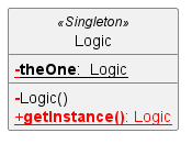
The <<Singleton>> in the class above uses the UML stereotype notation, which is used to (optionally) indicate the purpose or the role played by a UML element. In this example, the class Logic is playing the role of a Singleton class. The general format is <<role/purpose>>.


Exercises:

Statements about the Singleton pattern


W10.3d

Design → Design Patterns → Singleton → Implementation

Can apply the Singleton design pattern

Here is the typical implementation of how the Singleton pattern is applied to a class:

class Logic {
    private static Logic theOne = null;

    private Logic() {
        ...
    }

    public static Logic getInstance() {
        if (theOne == null) {
            theOne = new Logic();
        }
        return theOne;
    }
}

Notes:

  • The constructor is private, which prevents instantiation from outside the class.
  • The single instance of the singleton class is maintained by a private class-level variable.
  • Access to this object is provided by a public class-level operation getInstance() which instantiates a single copy of the singleton class when it is executed for the first time. Subsequent calls to this operation return the single instance of the class.

If Logic was not a Singleton class, an object is created like this:

Logic m = new Logic();

But now, the Logic object needs to be accessed like this:

Logic m = Logic.getInstance();

W10.3e

Design → Design Patterns → Singleton → Evaluation

Can decide when to apply Singleton design pattern

Pros:

  • easy to apply
  • effective in achieving its goal with minimal extra work
  • provides an easy way to access the singleton object from anywhere in the code base

Cons:

  • The singleton object acts like a global variable that increases coupling across the code base.
  • In testing, it is difficult to replace Singleton objects with stubs (static methods cannot be overridden).
  • In testing, singleton objects carry data from one test to another even when you want each test to be independent of the others.

Given that there are some significant cons, it is recommended that you apply the Singleton pattern when, in addition to requiring only one instance of a class, there is a risk of creating multiple objects by mistake, and creating such multiple objects has real negative consequences.


Facade pattern

W10.3f

Design → Design Patterns → Facade Pattern → What

Can explain the Facade design pattern

Context

Components need to access functionality deep inside other components.

The UI component of a Library system might want to access functionality of the Book class contained inside the Logic component.
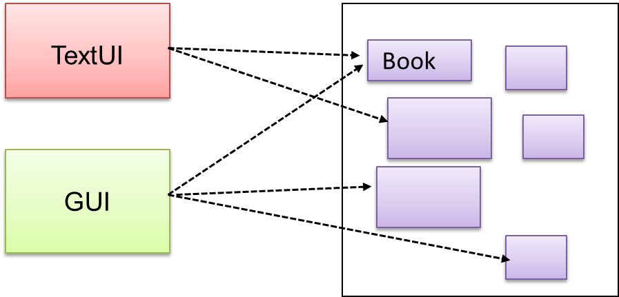
Problem

Access to the component should be allowed without exposing its internal details. e.g. the UI component should access the functionality of the Logic component without knowing that it contains a Book class within it.
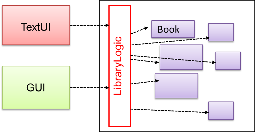
Solution

Include a class that sits between the component internals and users of the component such that all access to the component happens through the Facade class.

The following class diagram applies the Facade pattern to the Library System example. The LibraryLogic class is the Facade class.


Exercises:

Is this Facade?


Follow up notes for the item(s) above:

To learn more design patterns, you can refer to https://se-education.org/se-book/designPatterns/


Guidance for the item(s) below:

Previously, you learned how to write JUnit tests. How do you know which parts of the code is being tested by your tests? That's where test coverage comes in.

[W10.4] Testing: Test Coverage

W10.4a

Quality Assurance → Testing → Test Coverage → What

Can explain test coverage

Test coverage is a metric used to measure the extent to which testing exercises the code i.e., how much of the code is 'covered' by the tests.

Here are some examples of different coverage criteria:

  • Function/method coverage : based on functions executed e.g., testing executed 90 out of 100 functions.
  • Statement coverage : based on the number of lines of code executed e.g., testing executed 23k out of 25k LOC.
  • Decision/branch coverage : based on the decision points exercised e.g., an if statement evaluated to both true and false with separate test cases during testing is considered 'covered'.
  • Condition coverage : based on the boolean sub-expressions, each evaluated to both true and false with different test cases. Condition coverage is not the same as the decision coverage.

if(x > 2 && x < 44) is considered one decision point but two conditions.

For 100% branch or decision coverage, two test cases are required:

  • (x > 2 && x < 44) == true : [e.g. x == 4]
  • (x > 2 && x < 44) == false : [e.g. x == 100]

For 100% condition coverage, three test cases are required:

  • (x > 2) == true , (x < 44) == true : [e.g. x == 4] [see note 1]
  • (x < 44) == false : [e.g. x == 100]
  • (x > 2) == false : [e.g. x == 0]

Note 1: A case where both conditions are true is needed because most execution environments use a short circuiting behavior for compound boolean expressions e.g., given an expression c1 && c2, c2 will not be evaluated if c1 is false (as the final result is going to be false anyway).

  • Path coverage measures coverage in terms of possible paths through a given part of the code executed. 100% path coverage means all possible paths have been executed. A commonly used notation for path analysis is called the Control Flow Graph (CFG).

Consider the following Java method.

void findRate(int input) {
    if (input == 0) {
        return 0;
    }
    cap = 100/input;
    if (cap < 0) {
        return -1;
    } else {
        return cap;
    }
}

It has 3 paths, as follows:

  1. enter -> 2 -> 3 -> exit (can be triggered by input 0)
  2. enter -> 2 -> 5 -> 6 -> 7 -> exit (can be triggered by input -5)
  3. enter -> 2 -> 5 -> 6 -> 9 -> exit (can be triggered by input 8)

So, to achieve 100% path coverage, we need at least 3 test cases (e.g., 0, -5, 8).

A loop can increase the path count greatly.

void sayHello(List<String> names) {
    for (String n : names) {
        System.out.println(n);
    }
}

The number of paths through this method is very large, as each possible length of names produces a unique path.

  1. enter -> 2 -> exit (if names is empty)
  2. enter -> 2 -> 3 -> exit (if names has one entry)
  3. enter -> 2 -> 3 -> 2 -> 3 -> exit (if names has two entries) 1 ...

So, achieving 100% path coverage of this method will be extremely difficult.

  • Entry/exit coverage measures coverage in terms of possible calls to and exits from the operations in the SUT.
    Entry points refer to all places from which the method is called from the rest of the code i.e., all places where the control is handed over to the method in concern.
    Exit points refer to points at which the control is returned to the caller e.g., return statements, throwing of exceptions.

Exercises:

Highest intensity coverage


Guidance for the item(s) below:

Learn how to measure test coverage in your tP. You will be asked to demo that in the coming tutorial.

W10.4b

Quality Assurance → Testing → Test Coverage → How

Can explain how test coverage works

Measuring coverage is often done using coverage analysis tools. Most IDEs have inbuilt support for measuring test coverage, or at least have plugins that can measure test coverage.

Coverage analysis can be useful in improving the quality of testing e.g., if a set of test cases does not achieve 100% branch coverage, more test cases can be added to cover missed branches.

Measuring code coverage in IntelliJ IDEA (watch from 4 minutes 50 seconds mark)