What
A model is a representation of something else.
A class diagram is a model that represents a software design.
A model provides a simpler view of a complex entity because a model captures only a selected aspect. This omission of some aspects implies models are abstractions.
A class diagram captures the structure of the software design but not the behavior.
Multiple models of the same entity may be needed to capture it fully.
In addition to a class diagram (or even multiple class diagrams), a number of other diagrams may be needed to capture various interesting aspects of the software.
How
In software development, models are useful in several ways:
a) To analyze a complex entity related to software development.
Some examples of using models for analysis:
- Models of the can be built to aid the understanding of the problem to be solved.
- When planning a software solution, models can be created to figure out how the solution is to be built. An architecture diagram is such a model.
b) To communicate information among stakeholders. Models can be used as a visual aid in discussions and documentation.
Some examples of using models to communicate:
- You can use an architecture diagram to explain the high-level design of the software to developers.
- A business analyst can use a use case diagram to explain to the customer the functionality of the system.
- A class diagram can be reverse-engineered from code so as to help explain the design of a component to a new developer.
c) As a blueprint for creating software. Models can be used as instructions for building software.
Some examples of using models as blueprints:
- A senior developer draws a class diagram to propose a design for an OOP software and passes it to a junior programmer to implement.
- A software tool allows users to draw UML models using its interface and the tool automatically generates the code based on the model.
UML Models
Unified Modeling Language (UML) is a graphical notation to describe various aspects of a software system. UML is the brainchild of three software modeling specialists James Rumbaugh, Grady Booch and Ivar Jacobson (also known as the Three Amigos). Each of them had developed their own notation for modeling software systems before joining forces to create a unified modeling language (hence, the term ‘Unified’ in UML). UML is currently the most commonly used modeling notation used in the software industry.
The following diagram uses the class diagram notation to show the different types of UML diagrams.

source:https://en.wikipedia.org/
OO Structures
An OO solution is basically a network of objects interacting with each other. Therefore, it is useful to be able to model how the relevant objects are 'networked' together inside a software i.e. how the objects are connected together.
Given below is an illustration of some objects and how they are connected together. Note: the diagram uses an ad-hoc notation.
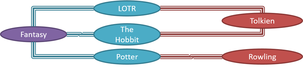
Note that these object structures within the same software can change over time.
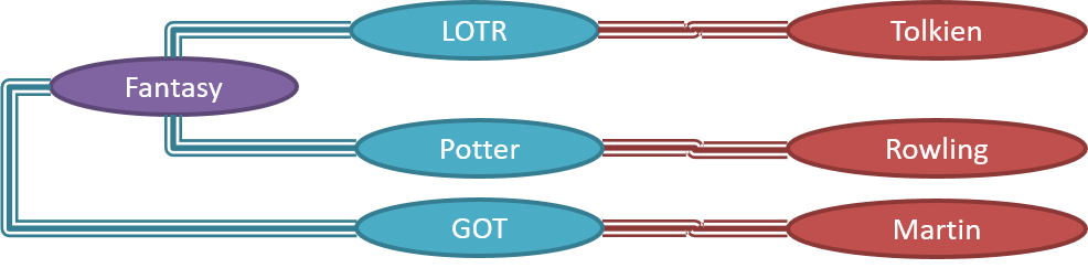
Given below is how the object structure in the previous example could have looked like at a different time.
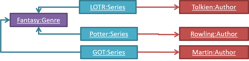
However, object structures do not change at random; they change based on a set of rules set by the designer of that software. Those rules that object structures need to follow can be illustrated as a class structure i.e. a structure that exists among the relevant classes.
Here is a class structure (drawn using an ad-hoc notation) that matches the object structures given in the previous two examples. For example, note how this class structure does not allow any connection between Genre objects and Author objects, a rule followed by the two object structures above.

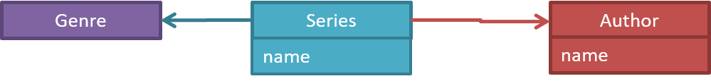
UML Object Diagrams model object structures. UML Class Diagrams model class structures.
Here is an object diagram for the above example:
And here is the class diagram for it:
Class Diagrams (Basics)
Contents related to UML diagrams in the panels given below belong to a different chapter (i.e., the chapter dedicated to UML); they have been embedded here for convenience.
Classes form the basis of class diagrams.
Associations are the main connections among the classes in a class diagram.
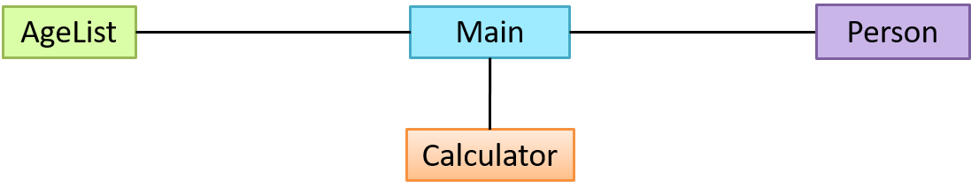
The most basic class diagram is a bunch of classes with some solid lines among them to represent associations, such as this one.
An example class diagram showing associations between classes.
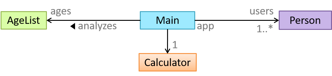
In addition, associations can show additional decorations such as association labels, association roles, multiplicity and navigability to add more information to a class diagram.
Here is the same class diagram shown earlier but with some additional information included:
Sequence Diagrams - Basic
Sequence diagrams model the interactions between various entities in a system, in a specific scenario. Modelling such scenarios is useful, for example, to verify the design of the internal interactions is able to provide the expected outcomes.
Some examples where a sequence diagram can be used:
To model how components of a system interact with each other to respond to a user action.
To model how objects inside a component interact with each other to respond to a method call it received from another component.
Contents related to UML diagrams in the panels given below belong to a different chapter (i.e., the chapter dedicated to UML); they have been embedded here for convenience.